Geoelectric Field Monitoring
We are currently running surface electric field monitoring systems at the three UK observatories (Eskdalemuir, Lerwick & Hartland) to measure the changing electric field generated near the Earth's surface.
Monitoring the electric field is important for validation of models derived by the team and which are used to predict potentially damaging geomagnetically induced currents in the power grid.
Data are recorded at 1 Hz along East-West and North-South electrode lines and automatically transmitted back to our office in Edinburgh for analysis and near real-time display.
Background
To understand how space weather impacts the grid, BGS has a model of the surface electric field, induced by rapid geomagnetic variations, coupled to a DC model of the UK's power transmission system. The electric field is the source of electrical currents flowing in the Earth's crust (Telluric currents) and these can damage transformers in the power grid. However, the electric field was not previously measured routinely anywhere in the UK.
We have now installed electric field monitoring equipment for long-term measurements at the three UK magnetic observatories. These data will be used to help constrain electric field models and, as a result, improve the prediction of induced currents in the UK power system.
Hardware
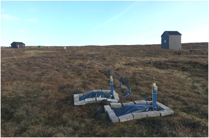
Measurements of the electric field are made by recording the voltage difference between two points in the ground, separated by a known distance in a given orientation.Two electrode pairs are used in a North-South and East-West configuration to capture the strength and direction of the surface electric field vector. The electrodes are spaced approximately 100m apart and are located as far as possible from sources of cultural noise and non-natural conductive structures (e.g. buried pipes and cables).
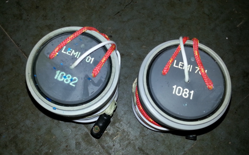
Non-polarising electrodes (LEMI-701, CuSO4 Chemistry) are used to make the voltage measurement as they prevent any self-potential effects caused by the interaction of the electrode conductor with the surrounding soil, and offer very good stability for long term measurements. They are buried at a depth of at least 70 cm to reduce temperature fluctuations and transient soil-conductivity changes due to heavy rainfall.
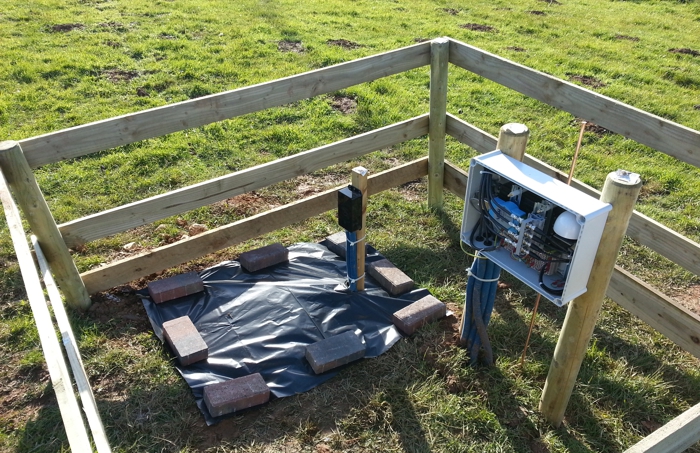
Voltage measurements are made via a 24-bit analog to digital convertor (Earthdata, PS-2400) that has an output rate of 50 Hz and data resolution of 1 μV. These data are then digitally filtered (using a Windowed-Sinc kernel) to produce 10 Hz samples.
These are collated in hourly files and automatically transmitted, every 10 minutes,
back to a BGS data server in Edinburgh.
Deployment
Installation at Eskdalemuir observatory was completed in November 2012, Lerwick observatory in March 2013 and Hartland in May 2013.
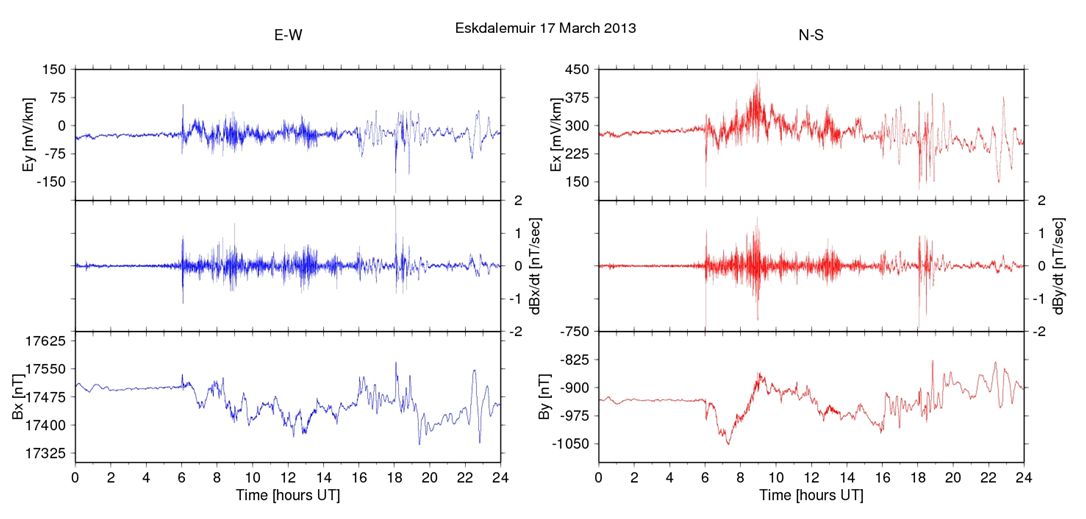
Plots of the electric field data are generated alongside magnetic data from the UK observatories for comparison and analysis. These data are available online.
National Astronomy Meeting 2013
This work was presented at the Royal Astronomical Society (RAS) National Astronomy Meeting 2013 at St. Andrews, Scotland.
Poster
RAS Press Release
Podcast
Acknowledgements
This project was funded by the BGS Opportunities Fund 2012. Ongoing operations are supported by NERC National Capability funding.
Contact
For more information please contact Dr Gemma Richardson.
- Global Geomagnetic Models
- Space Weather and Geomagnetic Hazard
- High-frequency magnetometers
- Schumann Resonances
- Geoelectric field monitoring
- Space Weather Impact on Ground-based Systems (SWIGS)
- SWIMMR Activities in Ground Effects (SAGE)
- Geomagnetic Virtual Observatories
- Quantum magnetometers for space weather
- Magnetotellurics
- Publications List
